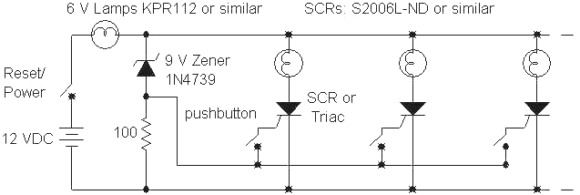
Quiz Buzzer Circuit Diagram. The Bridge rectifier is a circuit, which converts an ac voltage to dc voltage using both half cycles of the input ac voltage. Screw Connectors and DC Jack's are externally connected to switches.

In this paper we will see how the circuit design is made and how the buzzer works and displays the information on the screen.
I need LED instead of a buzzer.
Secret Diagram: Electronic quiz buzzer circuit diagram

Quiz Buzzer - FrugalPhysics
beeper buzzer circuit Page 2 : Audio Circuits :: Next.gr
School/College Quiz Buzzer | Full Circuit Diagram with ...

2-1 Quiz Buzzer Circuit Diagram

2-1 Quiz Buzzer

Game Buzzer Circuit

(PDF) Quiz Game Controller

4 Player #quiz #buzzer | Simple electronic circuits ...
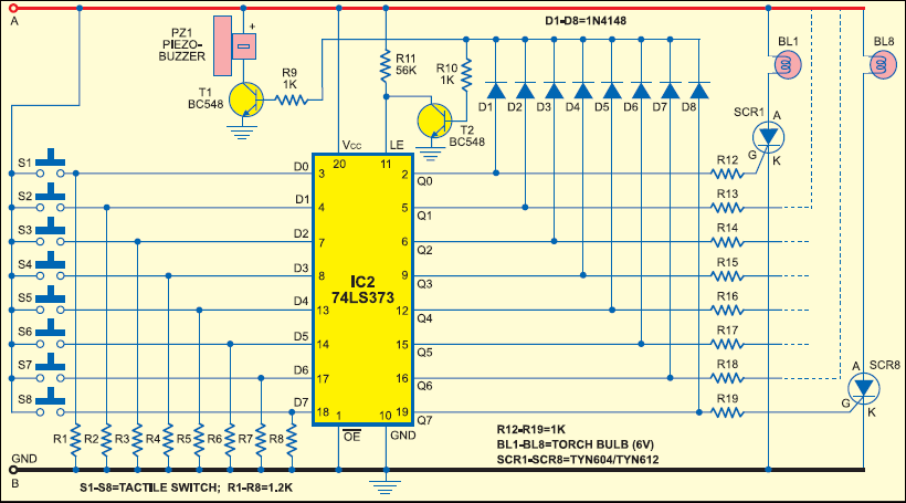
Match the circuit diagram symbol with the electronic component it represents. This circuit is a simple buzzer circuit and it called novel buzzer. I don't need any reset switch.
