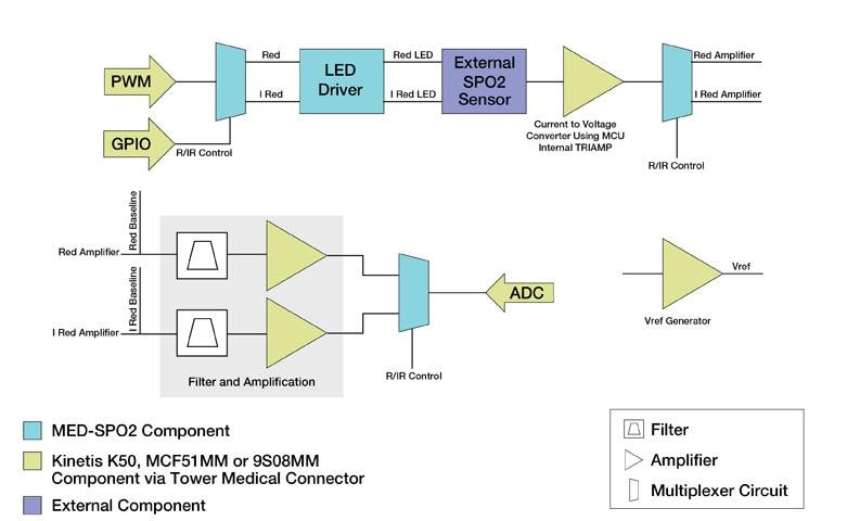
Pulse Oximeter Circuit Diagram. General Pulse Oximeter Circuit Diagram from publication: An Advanced Architecture & Instrumentation for Developing the System of Monitoring a Vital Sign (Oxygen Saturation) of a Patient. The main sections of this block diagram are now described.

A pulse oximeter is a device used to monitor both your heart rate and blood oxygen concentration.
The electronic circuits within the pulse oximeter do not require scheduled calibration or service.

Patent US8366613 - LED drive circuit for pulse oximetry ...
Measuring heart rate and blood oxygen levels for portable ...

Improve Sensor Performance and SNR in Pulse Oximeter ...

Pulse Oximeter design solution from Maxim Integrated
Pulse Oximeter Development Kit | NXP
Analog circuit for pulse oximeter transmitter unit ...

Pulse Oximeter Signal Conditioning Circuit | Download ...

Adding Heart-Rate Monitoring Functionality to Fitness Gear
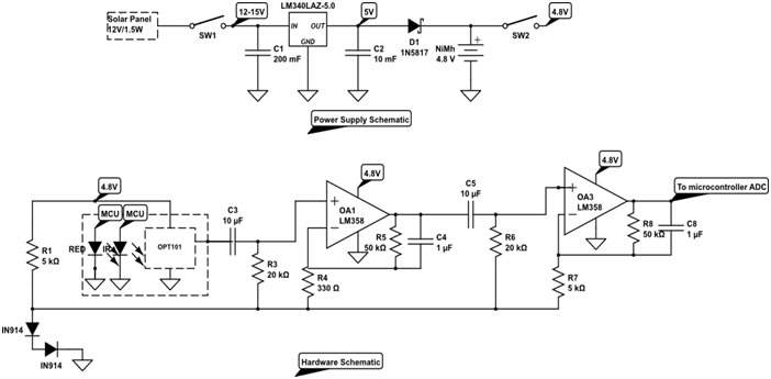
Solar Powered Pulse Oximeter and Heart Rate Meter (Parin ...
Pulse oximetry is based on the principle that pulsatile blood absorbance of IR or red light changes with regard to degree of oxygenation. Complete working of the Missing Pulse Detector Circuitry is shown in the video given at the end. Developed pulse oximeters require: Accurate sensor measurement to derive oxygen saturation levels and heart rate.
