Pulse Oximeter Schematic Diagram. Developed pulse oximeters require: Accurate sensor measurement to derive oxygen saturat. Share Link: Embed Code: pulse oximeter.

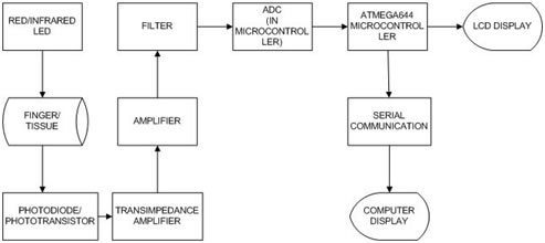
The prototype pulse oximeter constructed during this project consists of two hardware components and a programmed LabVIEW Virtual Instrument (VI).
Microchip can assist you with developing a broad range.

Infrared Pulse Sensor Schematic Abstract | Make: DIY ...
Pulse Oximeters - Maxim Integrated

97 Circuit Illustrations - N 20PA Pulse Oximeter
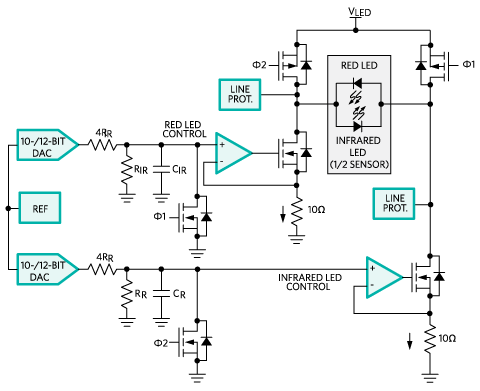
Pulse Oximeter Uses ADuC7024 MicroConverter | Analog Devices

APRS Position and Data Telemetry
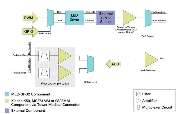
Pulse Oximeter Development Kit | NXP
Solar Powered Pulse Oximeter and Heart Rate Meter (Parin ...

Pulse Oximeters - Maxim Integrated

Simple Pulse Oximeter Circuit Diagram | Electronic ...
This timing mode would be used when heart rate is being measured with a single green LED. All designs include a schematic, test data and design files. Light is emitted from light sources which goes across the pulse oximeter probe and reaches the The above diagram shows both LEDs lit to make the explanation easier.
